Attempts at Curved Rail Timelapse Mechanism (9/12/2015)
First a little context:
Years ago, creating a programmable moving platform for timelapse and video was challenging. Most efforts were by photography and electronics enthusiasts. Online communities like the now defunked openmoco gathered user submitted motion control projects. I first discovered platforms like The Chronos Project, miniEngine and eMotimo while loitering around the projects pages and forums. These projects, and others like it have become commercially available as photography, film making and camera motion control becomes more accessible to anyone.

First version of Panning camera platform, 2012
Version 3 of Panning Camera Platform, 2015


Creating a moving timelapse slider presented many new challenges. Transferring the rotating motion of a motor shaft to the linear movement of a carriage on a rail means customizing existing parts and making up completely new parts. My first attempt at involved alot of hard cutting and shaping of plastic and metal grinding. I used a lead screw to drive the carriage across the rail. It has since been refurbished with 3d printed parts and still works great.
I became interested in adding another axis of movement to the sliding rail. I used two motor controllers (A chronocontroller a miniEngine V1) and a hastily made panning head mated to the slider carriage. It wasn't pretty, but it did the job. Still, adding another movement would be interesting, especially if that movement held a light!
Successful timelapse needs many things, but the most important is the lapsing of time! The trouble is, some indoor scenes and galleries don't give you enough of a sense of time passing. Little to no natural light means shadows don't change much or at all. It's all about the shadows!
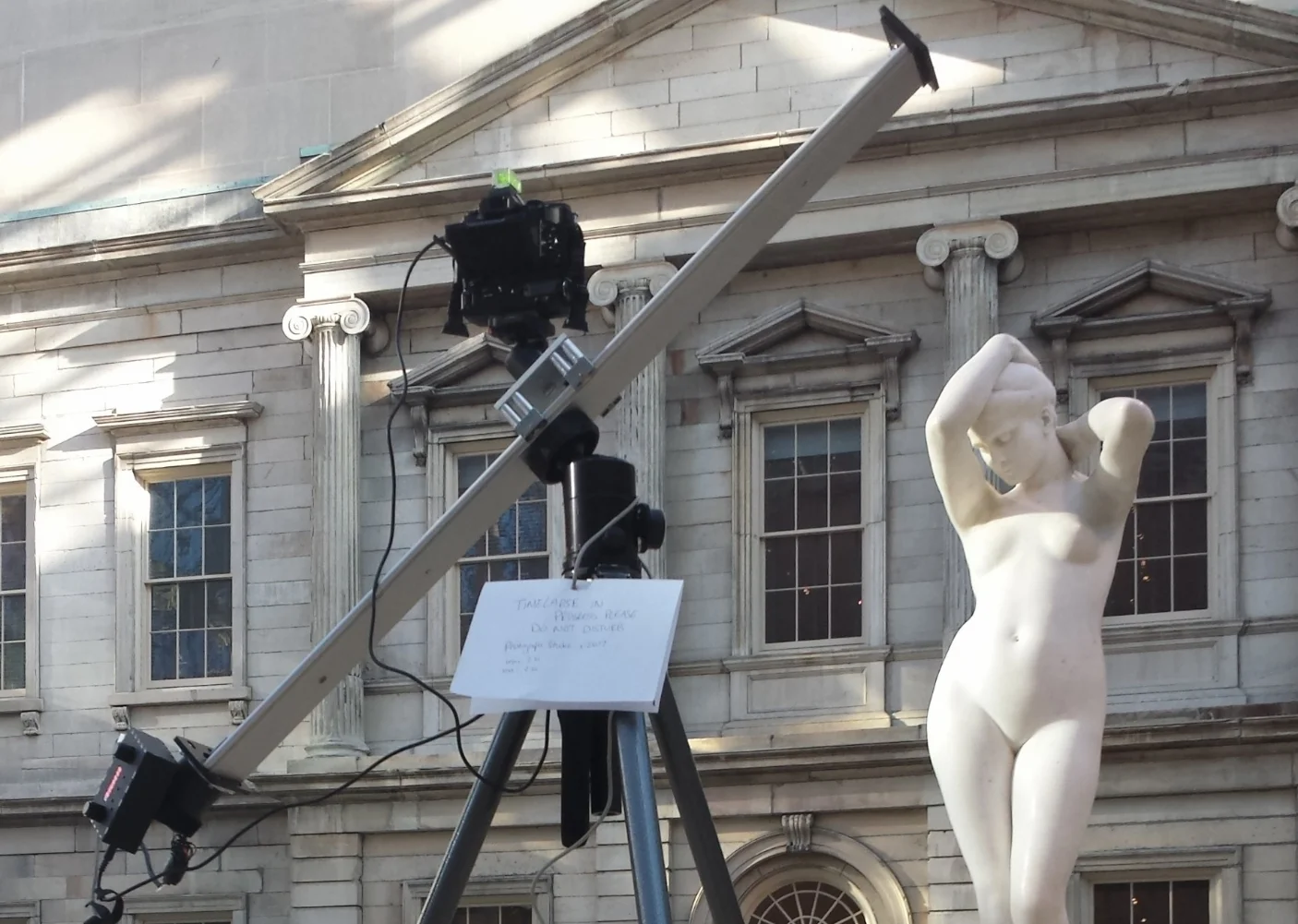
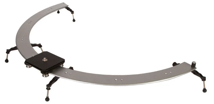
I thought adding a curved rail with an LED light could simulate an interesting light movement. even more interesting is the possibility of an orbiting timelapse. Using the curved rail for this kind or automation is difficult. Attempts and solving this problem has lead to frustration and a very messy desk.
It also lead to much on the job training in modelling 3D parts and assemblies.

Internals of pulley. Multiple spools helped maintain tension against the motor pulley.
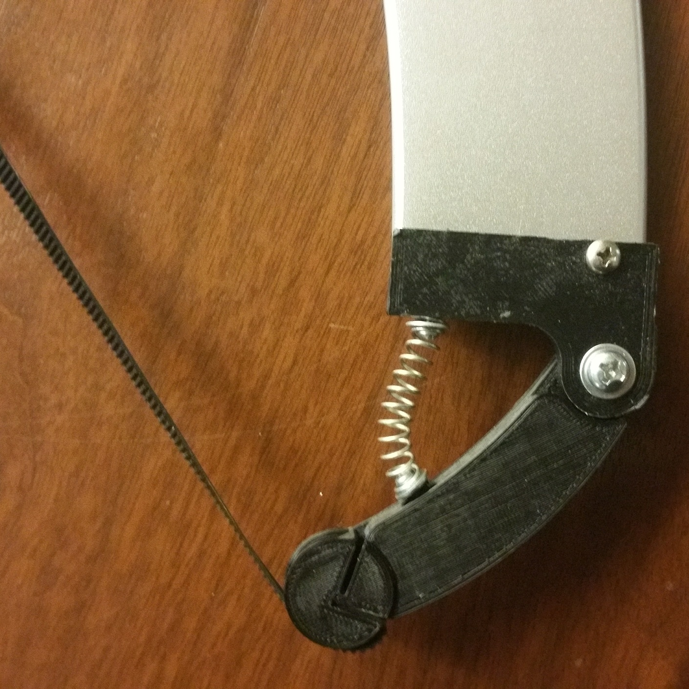
Spring loaded rail end caps help shift tension while the carriage moved towards it. Ultimately this is where this design failed.
Designing a solution
Initially, I thought of making a large, curving gear rack that followed the shape of the rail. I could simply mount a motor to the side of the carriage, a few gears and done! At the time the gear rack proved difficult to design, and mounting the motor on the side wouldn't allow me to use the entire rail. The next attempt involved pullies, a G2 belt and springs! It didn't exactly work as planned, but who doesn't like pullies and springs!?
After taking some time off, I decided to attempt the original Curved rack gear idea, integrating some lessons learned from the pully failure.


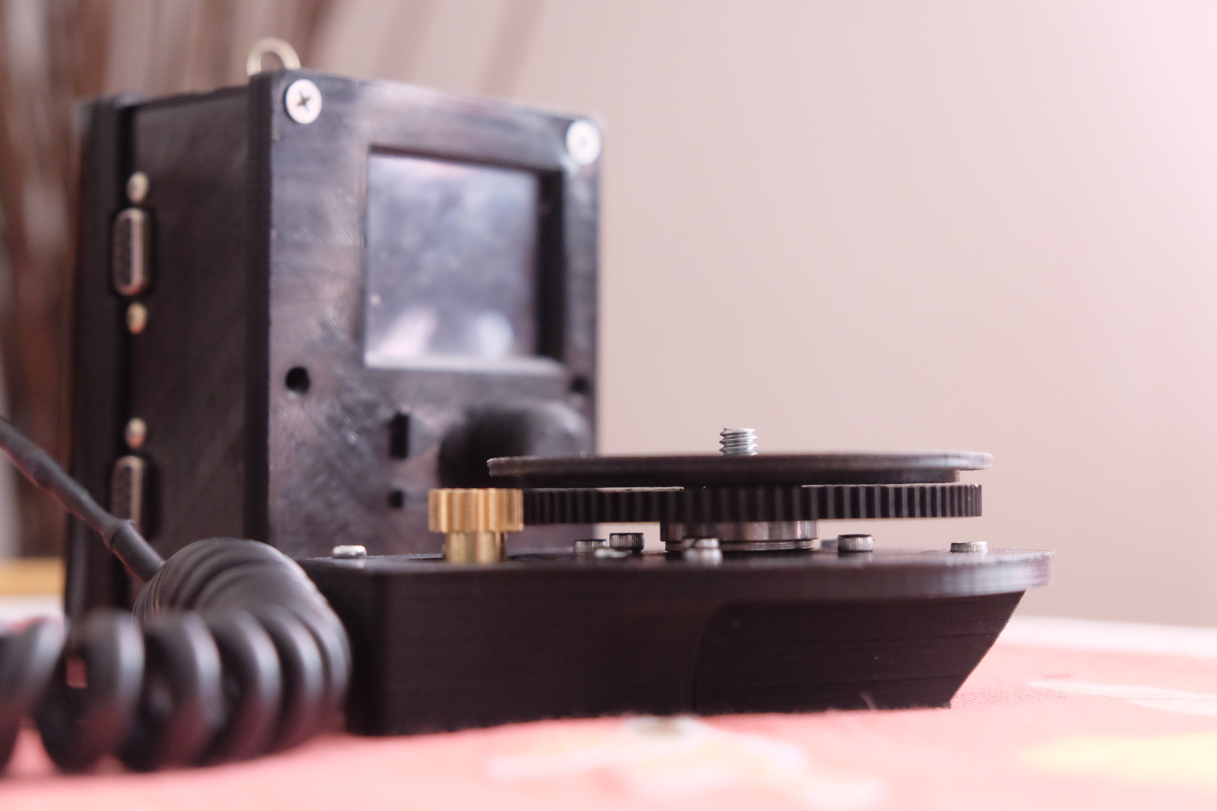
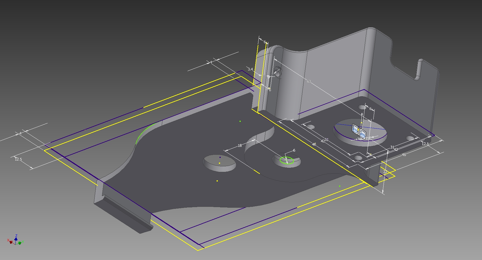
Making a plate to mount the motor at the head of the carriage instead of the side meant it could use the entire length of the rail. Using two gears to reach the curved rack increased torque and allowed the motor to be mounted off of the carriage plate, instead of reaching over it.

The curved rack was still an issue, but I eventually figured out the settings I needed for the size I wanted. The rear rack had to be sliced into pieces small enough to be printed on my machine. Printing gears has been tricky due to the nature of current FFF 3D printing, but I think I've gotten it to a good place.
By designing the parts and assembling them virtually before printing, I'm able to anticipate problems and allow the design to evolve much faster.
For example, I initially designed the gears with a smaller tooth. This worked in the 3D model, but didn't account for the small inconsistencies that happen in the printing process. I decided to redesign the gear teeth to be larger, and to be more forgiving to imperfections in the printing and assembly process.

Larger teeth and post assembly adjustment brace on the carriage allow for fine tuning after printing.
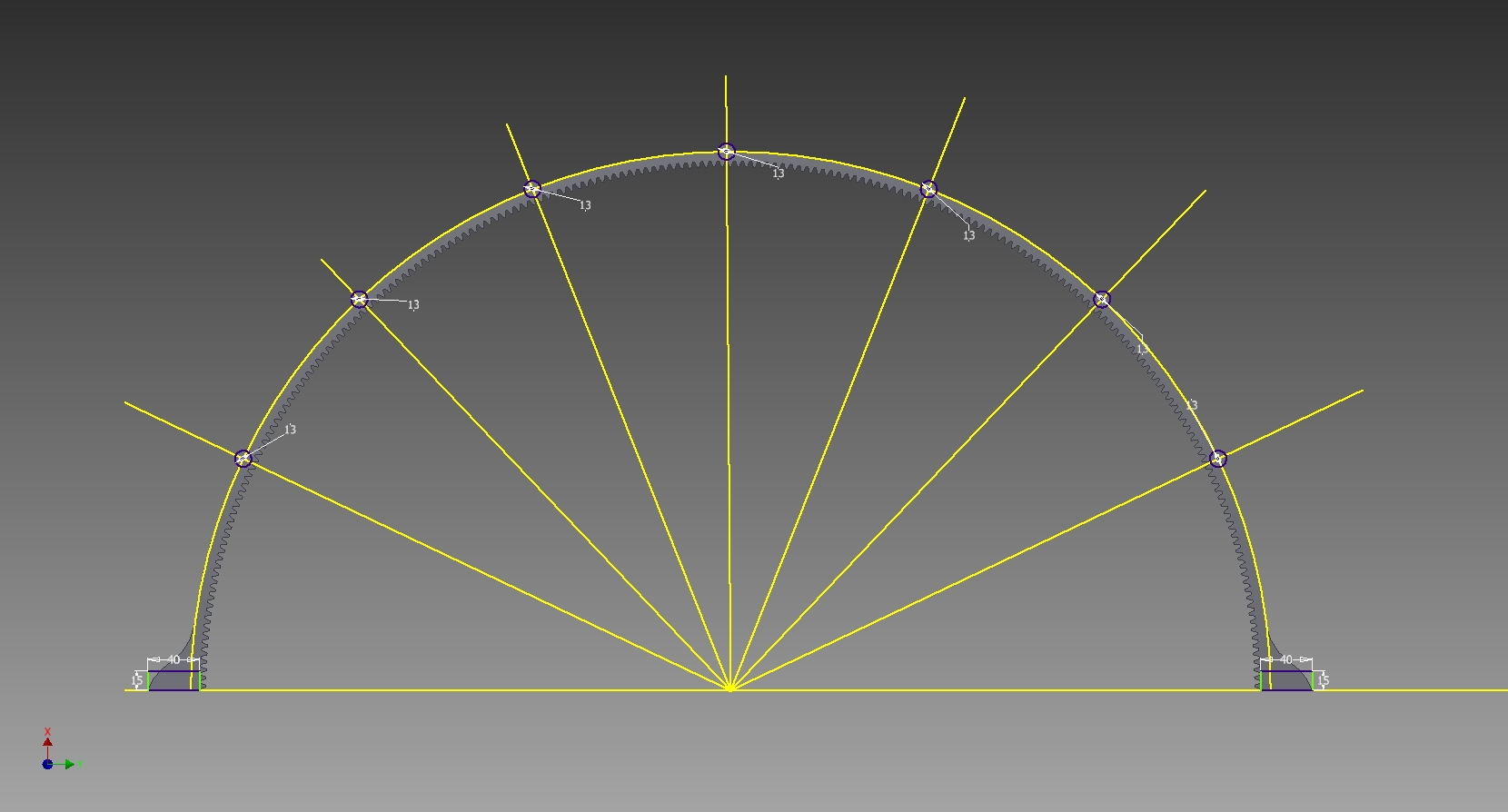
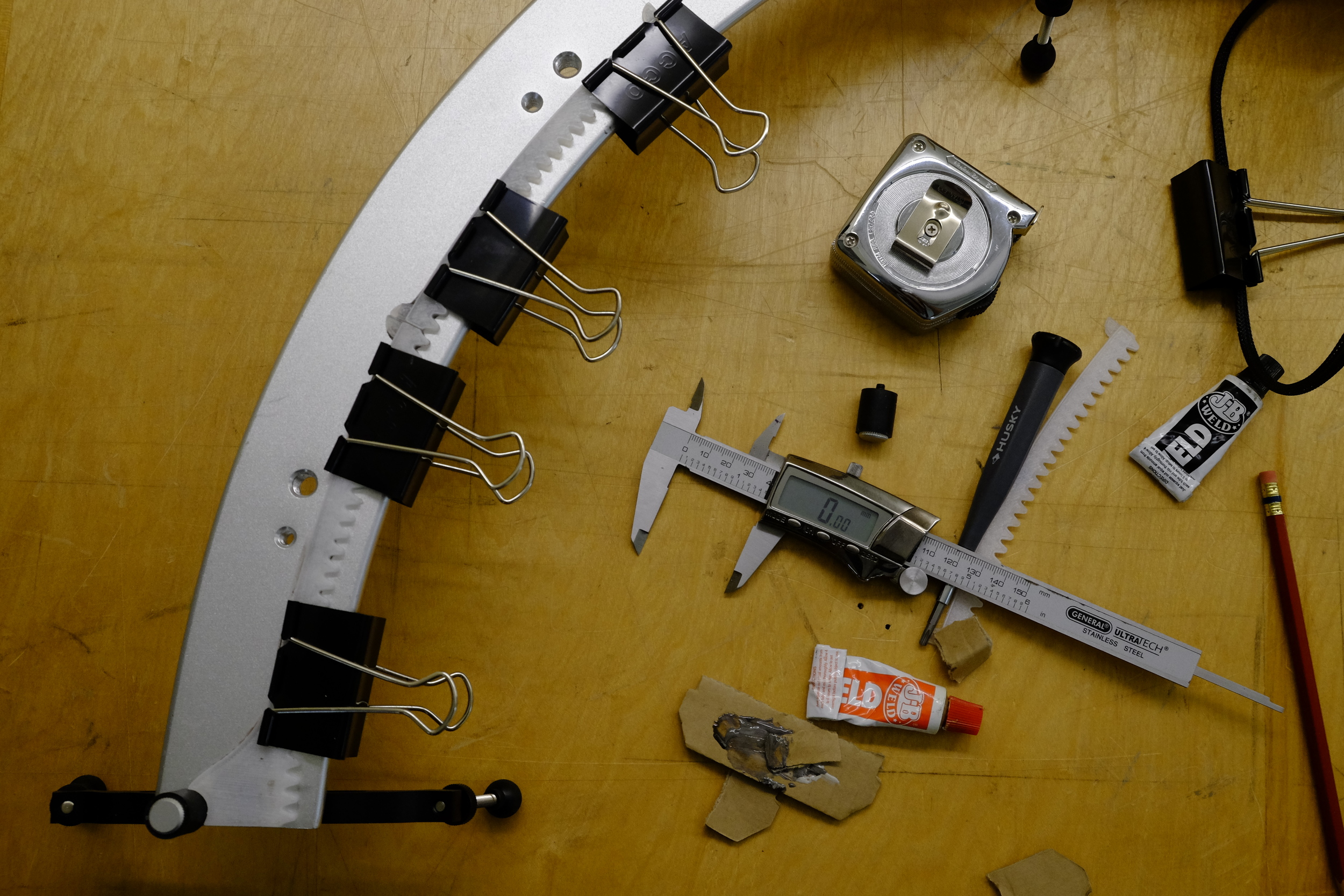
Large Rack gear sliced into 8 pieces for printing.
The large rack gear needed to be sliced up into 8 pieces in order to be printed at home. The gear rack pieces were attached to the rail with JB Weld. The first tests looked promising! The spacing of all the gears were pretty accurate to the 3d models. A little slop is to be expected, but can be addressed with a small adjustments.

